Software specific classification basics
In this section, we give examples of how classification is enabled in different software, which you can also follow based on provided example files and/or use those to generate/update your own project templates.
Table of Content
Autodesk AutoCAD
Autodesk AutoCAD software has been used for a wide variety of drawing and modeling tasks, and it can also be used very successfully as a part of BIM/maintenance models to create information content, but because it does not support property set functionality that can be exported to an IFC file, then it will not be covered further in this chapter. However, we will come back to it through AutoCAD vertical products such as AutoCAD Architecture, AutoCAD MEP and Autodesk Civil 3D, because general 2D/3D components can be classified in these vertical products. Additionally, it is important to note that since many other software use AutoCAD software as their base platform, pay attention to how classification is enabled in these add-on products (or plugins).
AutoCAD Architecture / MEP / Autodesk Civil 3D
AutoCAD Architecture / MEP and Autodesk Civil 3D are common building component-based building information modeling platforms. They are widely used both independently and through additional software that use them as their base platform (e.g., Architecture / MEP platform: hsbcad, MagiCAD; Autodesk Civil 3D platform: Trimble Novapoint). In addition, they also support IFC export (e.g., IFC 4×3 export is now available for Civil 3D software, which now support infrastructure components).
With all the aforementioned three software, the so-called first-level classification can be used with functionality that can be defined through: Style Manager > Multi-purpose Objects > Classification Definitions, where we find the CCI / CCI-EE construction components classifiers already predefined (see figure).

Please note that the given example uses the attribute naming scheme that starts with a code (2 letters, 3 numbers, e.g. AC175_ in the previous image). These names are defined in the CIA-DD database, where you can also find the definition of the attribute and the original source and/or connections to other attributes (e.g., ETIM, IFC properties). In addition to the code, some descriptive text is provided (underscore separates those two parts). The purpose of the text part is to ensure human readability. At the same time, neither punctuation nor spaces or extra dashes are used. As previously marked, the names of the attributes are in place with the exchange information requirements.
Back to the Classification Definitions section. Its main functionality is to create connections between the main classifier and the property set. In other words, if a component in the drawing is classified with a specific code, only specific property sets can be added to it. So, it works as a filter in a situation where we have maybe dozens of different property sets, each one for a very specific asset class. As an additional functionality, it can also be used in the situation when you want to export the general classifier to the IFC structure IfcClassificationReferences. However, it may not be supported by each IFC version (or software) (e.g., IFC 2×3 is OK, but not with IFC 4×3). Regardless, these two things are separate, and one does not interfere with the other.
Let me also highlight a simple example on how to set up a property set based on a classifier (note that this can make the Style Manager window very slow, especially if there are a lot of classifiers, as the software seems to spin through the entire list “on every move” , to find a certain check mark – but this is only in the Style Manager window and not while in the drawing).
So, make sure that AC175_ComponentClassCode is applied to those object groups where you want to use this functionality (a normal Property Set Definition cannot therefore use a group selection in the Applies To section that has not been added to the Applies To pane of the Classification Definitions section – the opposite situation is allowed). In the image below, most of the options starting with Civil Bridge are selected.

Now let’s move on to Property Set Definitions. And in this example, we’ll just use the two previously defined property groups, A001 and A010. At the first of these, A001, we specify that it can be used as the selected classifier ULD (you can also select several!).

Now, for the property group A010, let’s choose, for example, ULC.

Click OK and close the dialog. If you now select a component and specify either ULC or ULD as the classifier (in the upper part of the Properties palette), the content displayed in the Add Property Sets dialog will also change. In one case A010 is shown and in the other A001.

The AECPSDUTOATTACH command can also be used, after which all objects will be automatically assigned the property groups that are currently assigned to them (assumes that a classifier has been specified). Such a method makes it possible to simplify the inclusion of groups of properties if there are many of them and they depend on the type of object, which in turn is regulated by a specific CCI classifier. The added classifier can be used for automatic filling of certain properties, but already outside the Civil 3D software (including through the Dynamo interface, which will be discussed later).
In addition to the Classification Definitions section, CCI classifiers are also included in the sample drawing through the List Definitions options (see figure below). This allows attributes to be assigned a certain list of possible values.

The Style Manager dialog is also used to create different groups of properties (Property Set Definitions). The most important attributes related to the basic classification are also included in the sample drawing as an example. The name of a Property Set Definition (which can also be viewed as a data template) begins with the letter of the section from which the selected properties come, followed by a number that represents the group of selected properties in the data template. Thus, according to the need (exchange information requirements), different data templates can be prepared, which include different characteristics and thus also a different numerical part, in order to uniquely identify these groups/data templates (e.g., a data template based on a classifier/object type).
For example, properties related to general classification at the construction entity level are gathered under the data template A001, to which a textual part can also be added: A010_AdminEntity (see figure below). While most of the classification is still done at the element level, and for this there is a separate attribute group called A010_AdminElement. Please note that this textual part should be easy to understand (human readable) and not confusing. While the alphanumeric part (A001, A010) is primarily machine-readable.

It is possible to fill in certain properties automatically if some general classifier is marked in it. External applications can also be used for this purpose and then imported into Civil 3D software. It is also possible to automate some properties in the Property Set Definitions dialog, e.g., adding property values together to provide a reference identifier.

Property sets (Property Set Definitions) can be created uniformly across all objects, or differently based on the Applies To options, but in this case, the properties group names should also be distinct, so that they can be used more easily or applied automatically. In other words, the names of the group of properties must be carefully considered and the same names must be used in other software that supports the same logic, so that when it is imported what-so-ever IT system, their uniformity and comprehensibility are preserved. Property groups can also be classified by project stage, although one and the same property group can also be used as a universal one, we just don’t fill in information fields that are not yet known for project stage.
By following the previously stated principles, we can classify, identify, and add a type identifier to components, technical systems, etc. All of this would replace any previously used naming rules because there is no point in using the double system. It is true that in certain situations it may be necessary to assign some other ID value to the asset, which is based on the architecture of the used IT system and the asset register, but this can then be noted as an additional property that helps to transfer information from one system to another. And of course, some projects may also use different classification systems in parallel (e.g., parallel use of CCI-EE and Uniclass), but their parallel need must be clearly defined/communicated so that the user does not get confused.
Autodesk Revit
Autodesk Revit is first of all a package for modelling buildings, constructions and engineering-technical solutions inside buildings, which is also partially used in modelling outdoor areas (site plan, bridges, noise barrier walls, etc.). The classification system can be introduced here through the Project Parameters functionality, where we first define the properties through which we want to introduce the classifier or any other parameter related to it. There are several ways to do this. These properties can be defined in the project template, but they can be imported into the existing project from another project or from the project template (Manage > Transfer Project Standards). If desired, these properties can also be imported through the Shared Parameters file or use some additional plugin, which generally makes these imports more convenient (e.g. DiRootsOne ParaManager). In this case, we can more easily play around in which section we want to display these parameters (including indicating whether it is a type or a unique parameter). Shared Parameters is also important if we want to share these attributes with other project partners (who also use Autodesk Revit or GUID-based software – while, for example, Autodesk Architecture / MEP / Civil 3D use their own unique ID system, which is Handle).
At the same time, the GUID or Globally Unique Identifier is no longer important in the context of CCI, because our unique identifier will be precisely the name of the property of the CCI itself (2 letters + 3 numbers, see the introductory part above). In general, it is recommended that we first have these properties in the project and set them up in a way that determines where these properties are displayed.
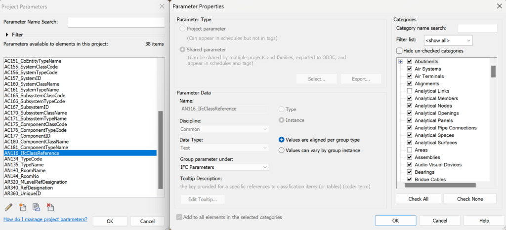
Below is an example where the property AC125_BSpaceClassCode (represents the CCI code of the built space) is only associated with the Autodesk Revit categories related to the spaces. Additionally, note that this property is included in the Identity Data section and marked as an Instance property, which means that it can be changed independently for all spatial objects (regardless of whether they are of the same type or not). Important! For certain groups, we can only use properties defined as Instance type (e.g., room objects).

In the previous examples, CCI-related properties are included under the Identity Data section. However, depending on the nature of the property (Instance or Type), these properties would be split between the Properties vs. Type Properties dialogs.
However, those properties that are not directly related to classification / identification are included under the Data section (even if the property itself would rather fit under another category that Autodesk Revit offers). In this case, it is easier to find them, because they are all in one place.
One CCI-related parameter (from the project template) also sits in the IFC Parameters section. This is the AN116_IfcClassReference parameter, which is filled in the form: CCI code: CCI concept (as they are written in the CCI-EE table, without the type/ID value, it is a main level classification, which moves to the correct section when IFC is exported, see later example).
We’ve already covered CCI-centric property input before. At this point, it is also worth noting that since these are Instance properties, it essentially means that we should fill in the corresponding cell for each selectable component, even if it is the same type. However, to make these entries easier (e.g., to attach the CCI main classifier QQA (Window) to the windows – i.e., as common properties, you can also use various Autodesk Revit functionalities for this, including Select All Instances (selection with a right click and then filling in the common properties on the Properties palette) or instead, do it through the specifications (Schedules tables). There are several possibilities. Since the classification involves a lot of information that is written in advance and we must choose the right value from the given list, and not type it in again every time (risk of typos), you can use additional plugins, one example we’ll look at below is the Autodesk Interoperability Tools.
Using Autodesk Interoperability Tools / Standardized Data
Although a classification system can also be implemented here simply by defining properties and filling them in, here we look at a separate plugin that allows you to include the content of an existing classification system more easily. For this purpose, the Standardized Data plugin is part of the Autodesk Interoperability Tools.
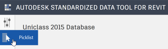
Let’s first see how the Standardized Data included in the Autodesk Interoperability Tools helps to make the classification system easier to use. Download the template (found in the download area, MS Excel file), open Autodesk Revit, make sure you have installed Autodesk Interoperability Tools, click: Standardized Data > Assign Classification (or Assign Picklist)

The Picklist button (top left) may not be visible at first launch.
Click on the first button Options and add an additional track where you can find downloaded or created additional templates (MS Excel files).

In the Picklists section, add addresses from your computer or network drive where MS Excel files can be found. Just an example below.

Alternatively, you can use directory marking through the *.ini file (see also the Autodesk manual), which must be located at C:\Program Files (x86)\Autodesk\AIT[Revit version] and contain the following content:
[Defaults]
ShowPublicDbs=true
LocalDbFolder=C:\01-taltech\30_Projects\CCI-EE\templates\standardized-data
After the Picklist button appears, Load New Pikclist, then check My Library section and select appropriate MS Excel file.

After making a selection, click OK. Then also click Click here to load to load the database.
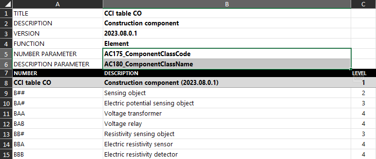
Next, you can proceed to classification. In other words, the CCI-EE tables are loaded through the plugin and displayed according to the nature of the selected element. It is important to note here that the selected tables help us to fill in precisely the main CCI classifiers (not the associated type/subtype). At the same time, Autodesk Interoperability Tools can be used “in parallel” with many different templates. In other words, through one template we fill in some specific information known at the project stage (e.g., some part of the information is known in a more general form already in the early stages of the project, “window is window”, “column is column”). Then another template may exist through which we can simplify filling the types. In addition, there may be a separate template through which property values resulting from content requirements can be filled in (as options from lists). These properties, which in our example are in the Data section. It should be noted that the template must be defined in such a way that each worksheet contains a project parameter reference, only then it can be filled in. It doesn’t really matter if the project parameter is Type or Instance. This tool simply looks for the specified property in the template and fills it with a selected value. Below is an example where the component’s CCI classifier is defined by two properties (see template worksheet CCI table CO, and upper lines NUMBER PARAMETER, DESCRIPTION PARAMETER).
You can essentially classify using this tool in three different main views (Facility, Element, Space). First, the Facility view. If no components are selected, then we are talking about the Construction complex or Construction entity level classification, and they generally move to the Project Information dialog.
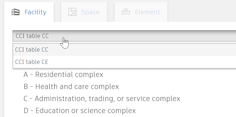
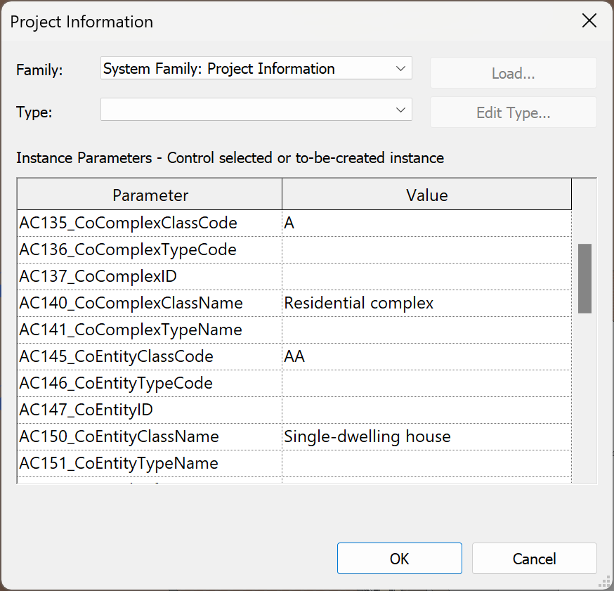
Now, if you first select either CCI table CC or CCI table CE from the Facility pop-up, we classify your building according to the construction complex/entity code. For example, let’s choose A – Residential complex as a complex. Then, at the bottom of the dialog, click Assign. Similarly, we can also make a selection in CCI table CE section, where we select AA – Single-dwelling house, for example. Again we click on the Assign button. This information is then displayed in the Project Information dialog.
Close the Project Information dialog. Run the classification tool from the Assign Classification button. Please note that if at some point it is necessary to reclassify components with already existing codes, you must remove the Options > Blanks only check box. Otherwise, the change is not executed.
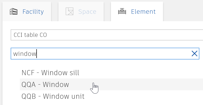
Now, if you move on to the Picklist section and select an element from 3D view, let’s say it’s a window, the Element pane is activated, and below it, in turn, there is a pop-up with various sub-tables of the classification system. You can now select/fill them one by one for the window.

Let’s choose CCI table CO for example. We can use the search word window, and then we can get to the desired section/code faster. We select it and click Assign.
Close the Standardized Data dialog. Select a window and check its properties. Note that the corresponding properties are filled in the Identity Data section.
With this, we have briefly familiarized ourselves with the nature of the Autodesk Interoperability Tools plugin Standardized Data. As a side note, you don’t have to close the corresponding dialog if you want to continue with the classification. Simply select the next element or a group of elements (Select All Instances > Visible in View), select the code you want to add and then Assign. Select a new group of elements and continue. You can view the CCI-EE tables on an ongoing basis to add other codes. Other methods can be used to enter the properties more easily, including through the Dynamo interface. However, it is important to note that the content is still filled in the Autodesk Revit file and not in the exported file. Therefore, Autodesk Revit and, for example, other formats derived from it (IFC, MS Excel export) must contain filled in properties in the same way. Otherwise, we enable a different interpretation of the data based on the selected file/data type.
Note. If you use an attribute as a Type based, all components of the same type will be filled in at the same time.
IFC export with the classification codes
Before going to a specific example, we need to understand how classification codes are displayed in IFC. At IFC, we can add the main level classifier to the IfcClassificationReference section (these are CCI codes, concepts that come from the CCI-EE table, without a type or ID value). It also creates a universal CCI-based classification in the IFC structure that helps filter geometry, transfer data, or otherwise view general-level information. While the rest of the properties (including those related to type, ID, and reference identifiers, as well as post-CCI properties presented by the content) are displayed in other sections.
To include the IfcClassificationReference relationship, a property called AN116_IfcClassReference has been added to the project template. We include this property under IFC Parameters in the active project.
We can also prepare a Standardized Data template to fill it in, but in this case, we just fill it in manually. The entry of the parameter is based on the logic that CODE: Term. So, for example, to describe a window, we fill in the corresponding field as: QQA: Window (both variants should work, whether a space is placed after the colon or not).

Before IFC export, we still need to specify where the IfcClassificationReference part is read from. To do this, select File > Export > IFC. We will edit the setting <In-Session Stup>, but of course you can also create a new group of settings for this. Click Modify Setup > Property Sets > Classification Settings…
You can then enter various information regarding the classification system in use (including the version of the table, the web address where it comes from, etc.). Also note the box: Classification field name = AN116_IfcClassReference, it plays an important role in filling the IFC structure IfcClassificationReference.

Note. Classification Settings are assigned as follows (based on the IFC version):
IFC 2×3
- Name – IfcClassification.Name
- Source (Publisher) – IfcClassification.Source
- Edition – IfcClassification.Edition
- Edition date – IfcClassification.EditionDate (not exported in current version, IFC 2×3)
- Documentation location – IfcClassificationReference.Location
- Classification field name – parameter name from where class code and term are extracted (code:term)
As found from the exported IFC when opened in text editor:
- #1214108=IFCCLASSIFICATION(‘Ehituskeskus’,’2023.08.0.1′,#1214109,’CCI-EE’);
- #1214110=IFCCLASSIFICATIONREFERENCE(‘www.ehituskeskus.ee’,’QQA’,’Window’,#1214108);
IFC 4.x (IFC 4.3 does introduce some changes)
- #1214342=IFCCLASSIFICATION(‘Ehituskeskus’,’2023.08.0.1′,’2023-11-28′,’CCI-EE’,$,’www.ehituskeskus.ee’,$); (check IFC 4×3 defintion: webpage)
- #1214343=IFCCLASSIFICATIONREFERENCE(‘www.ehituskeskus.ee’,’QQA’,’Window’,#1214342,$,$); (check IFC 4×3 defintion: webpage)
Export the IFC file (ensure that you have selected valid property sets) and check the IFC in a viewer. We keep the same IFC viewer as before: Trimble Connect.

Please note that IFC viewer may show those parameter names differently:
- Location – www.ehituskeskus.ee – IfcClassificationReference.Location
- ItemReference – QQA – IfcClassificationReference.ItemReference
- Name – Window – IfcClassificationReference.Name
- RelatingClassification.Source – Ehituskeskus – IfcClassification.Source
- RelatingClassification.Edition – 2023.08.0.1 – IfcClassification.Edition
- RelatingClassification.Name – CCI-EE – IfcClassification.Name
Note different sections: Data and IfcClassificationReference
Usually, we do not need to present the same data twice. And it will be connected as much as possible (as shown before in where parameter value from IfcClassificationReference was read by a parameter in properties section). So, in this case it may be seen an unnecessary to include the window classification code under Data as well as under IfcClassificationReference. Hereby we want to point out the different ways to do it.
Pay attention to that different IFC viewer may present the same data in different sections. For example, BIMcollab does not have a section called IfcClassificationReference, instead it will reflect that part under the first tab, Summary.

Solibri Anywhere shows this data under Classification tab.

BIMvision shows this data under Classification tab as well.

In terms of construction entity/complex, this information is not shown directly but can be acquired from the IFC file as:
#141=IFCPROPERTYSINGLEVALUE('AC135_CoComplexClassCode',$,IFCTEXT('A'),$);
#142=IFCPROPERTYSINGLEVALUE('AC140_CoComplexClassName',$,IFCTEXT('Residential complex'),$);
#143=IFCPROPERTYSINGLEVALUE('AC145_CoEntityClassCode',$,IFCTEXT('AA'),$);
#144=IFCPROPERTYSINGLEVALUE('AC150_CoEntityClassName',$,IFCTEXT('Single-dwelling house'),$);
With this, we have familiarized ourselves with the technical side of classification using Autodesk Revit as an example. By following the previously stated principles, we can classify, identify, and add a type identifier to components, technical systems, etc. All of this would replace any previously used naming rules because there is no point in using the double system. It is true that in certain situations it may be necessary to assign some other ID value to the asset, which is based on the architecture of the used IT system and the asset register, but this can then be noted as an additional property that helps to exchange information from one system to another. And of course, some projects may also use different classification systems in parallel (e.g., parallel use of CCI-EE and Uniclass), but their need must be clearly defined/communicated so that the user does not get confused.