Example: Autodesk Civil 3D
In this section we carry out a basic classification on the example of a bridge, where we classify one component but also define it’s relation to technical system and functional system.
However, you can find a more complete picture in the downloadable Autodesk Civil 3D file, where all similar components are classified. To reuse those sample attributes you can use the same Civil 3D file. In addition, the RDS/R (types table) is in use, which lists the types/subtypes used in the classification.
Note. The types/subtypes of the RDS/R table must be based on a uniform set of rules, e.g. a distinct function that the element performs or some other distinct aspect. Types/subtypes can always be specified with product-specific attributes (additional attributes), so RDS/R table types/subtypes must not be viewed in the context of product/manufacturer or overly specific attributes. However, in some cases, the distinguishing type/subtype can be the context of the material if such a distinction is very fundamental (e.g. environmental aspect). The RDS/R types table presented here is client-wide (possible to use across various clients), i.e. if you look at the type tables on the example of one specific client, it is obvious that they do not need to expand all RDS/CCI core classifiers into types/subtypes, but to limit themselves only to the parts that are important to them.
Software example files: Software files
Note. The example file can be extended if additional component types/elements are included. At the moment, the main components of the architectural part are in focus.
Classification of a component
After RDS/CCI classification-related attributes are included in active project, those are displayed under the Extended Data pane of the Properties dialog. At the same time, it must be emphasized that with later addition, the corresponding attribute groups must be included to the objects through the Add Property Sets dialog. The drawing includes one main attribute group: A010_AdminElement (used to classify most components).
In the given examples, it is assumed that the required list of attributes is specified in the exchange information requirements. Some attributes are filled in individually, but with reference designation(s) or with unique ID, different values are combined into a single value (this can be automated, which will be discussed in further examples).
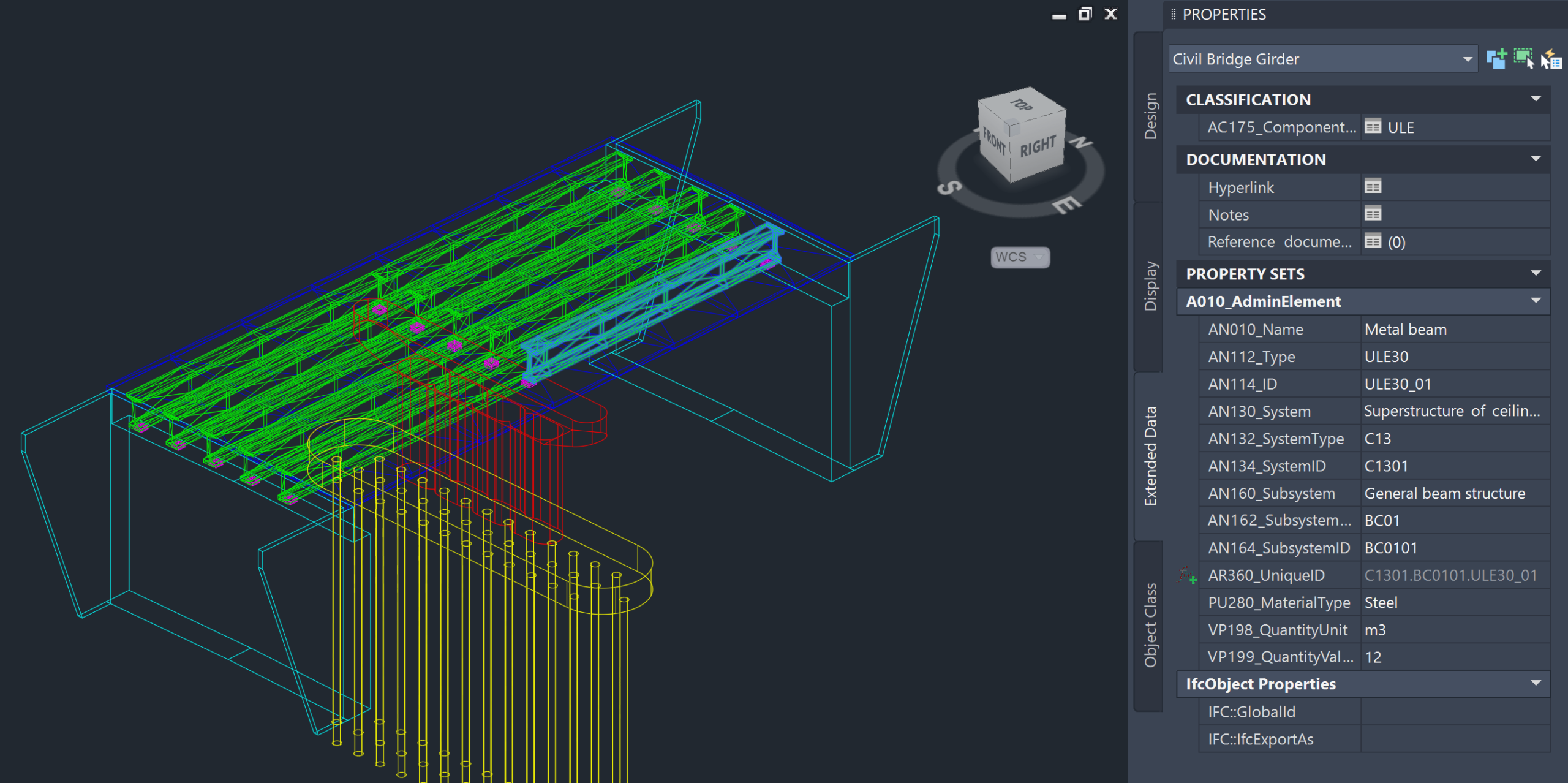
Using the example of a beam as a component, we will therefore go through the attributes shown in the previous image, which also stipulates the rules for fulfilling these attributes.
- AN010_Name – beam (type) name, which can be based on application tables (e.g. RDS/R). In this example: Metal beam
- AN112_Type – type code corresponding to the beam (type) name, which may be based on an existing application table (e.g. RDS/R). In this example: ULE30
- AN114_ID – a unique repetition of a specific beam (of its type). Uniqueness can come both across the entire construction entity, based on the type and its repetition, or also from the placement of a specific type of beam in a system/subsystem. The final part (separated by an underscore) can also be expanded to three digits if necessary. In this example: ULE30_01
Essentially, this is all that is needed to classify a specific beam. This is followed by the beam’s relationship to the system and/or subsystem (belonging). The relationship/belonging allows components to be filtered by system. The system presents a broader view, so to speak (more general, e.g. horizontal-vertical arrangement), while the subsystem presents a narrower view (generally descriptive through a technical solution). Let’s see an example of a system first.
- AN130_System – human-readable name of the system (type), which can be based on application tables (e.g. RDS/R) or also on the client’s asset lists, in here as: Superstructure of ceiling system
- AN132_SystemType – machine-readable code of a system (type) that corresponds to a human-readable name and is based on the same source as the name itself. In this example, as: C13
- AN134_SystemID – a unique ID for a specific system type, allowing for the distinction between equivalent system types (across the construction entity), in this example a two-digit number is used, which is written together with the system code. In this example as: C1301
Subsystems are “located” within systems, and their implementation follows similar principles to those of a system. The main difference is that the ID part now distinguishes unique subsystems within a particular system. So if the system changes, the subsystem can start again from the so-called “01” value. That is why components are classified into subsystems, and subsystems in turn into systems.
- AN160_Subsystem – human-readable name of the subsystem (type), which can be based on application tables (e.g. RDS/R) or also on the client’s asset lists, in here as: General beam structure
- AN162_SubsystemType – machine-readable code of a subsystem (type) that corresponds to a human-readable name and is based on the same source as the name itself. In this example, as: BC01
- AN164_SubsystemID – a unique ID for a specific subsystem type, allowing for the distinction between equivalent subsystem types (across a certain system), in this example a two-digit number is used, which is written together with the subsystem code. In this example as: BC0101
Once the component and its membership are defined, a unique ID value for a specific element can be created based on the individual values, which is based on RDS logic.
- AR360_UniqueID – this field contains individual ID values, which according to RDS logic are separated from each other by a period. In the given example as: C1301.BC0101.ULE30_01
Note. If necessary, the principles for creating a unique ID value can be changed, but this must be specified in the information requirements. For example, use an underscore for all ID values: C13_01.BC01_01.ULE30_01
Note. The unique ID value can also be supplemented with location-based or layout-related information.
In addition to the RDS/CCI classification attribute, some additional properties are included, with which we define, for example, the material category, the unit of base quantity calculation, and the quantity value (as a number, including the desired number of decimal places).
With this, we have presented an example of classification logic based on Autodesk Civil 3D. The components are different and thus the previously discussed principles must also be used in the classification of other objects. The software specifics and template structure are described in a later section.