Example: Autodesk Revit
Note. Autodesk Revit classification examples are presented in a way where all attributes are first defined in the Instance way. In certain situations, some attributes are also needed in the Type representation and will be addressed in later sections (e.g., transferring type-related attributes to the COBie information exchange format). Note that certain categories always assume an Instance attribute (eg Room, Project Information), so Instance is also the first choice in the examples here. At the same time, it is possible to include attributes in both the Instance and Type sections using the given Shared Parameters file, but it should be noted that some attributes are strictly Instance in nature, i.e. they present some ID value and therefore cannot belong to the Type section. Instance/Type based definition can be very software specific and may not be a topic at all in other software (e.g. Autodesk Civil 3D).
Software example files: Software files
Note. The example file can be extended if additional component types/elements are included. At the moment, the main components of the architectural part are in focus.
Contents
Building example
Below, we will carry out a basic classification exercise on the example of a building, where we will select one component, one technical system (with the functional system reference) and also the built space.
However, you can find a more complete picture in the downloadable Autodesk Revit file, where all similar components are classified, additional tables, etc. are included. The sample Revit file as well as the Shared Parameters file can be used to reuse attributes. In addition, the RDS/R (types table) is in use, which lists the types/subtypes used in the classification.
Note. The types/subtypes of the RDS/R table must be based on a uniform set of rules, e.g. a distinct function that the element performs or some other distinct aspect. Types/subtypes can always be specified with product-specific attributes (additional attributes), so RDS/R table types/subtypes must not be viewed in the context of product/manufacturer or overly specific attributes. However, in some cases, the distinguishing type/subtype can be the context of the material if such a distinction is very fundamental (e.g. environmental aspect). The RDS/R types table presented here is client-wide (possible to use across various clients), i.e. if you look at the type tables on the example of one specific client, it is obvious that they do not need to expand all RDS/CCI core classifiers into types/subtypes, but to limit themselves only to the parts that are important to them.
Building: Classification of a construction component
After RDS/CCI classification-related attributes are included in active project, those are displayed in the Properties > Identity Data section. Autodesk Revit is limited in that we can use built-in sections like Identity Data, IFC Parameters, Data etc. The display of attributes can be set based on the category of the object (e.g., it does not make sense to show an attribute related to a technical system for rooms).
In the given examples, it is assumed that the required list of attributes is specified in the exchange information requirements. Some attributes are filled in individually, but with reference designation(s) or with unique ID, different values are combined into a single value (this can be automated, which will be discussed in further examples).
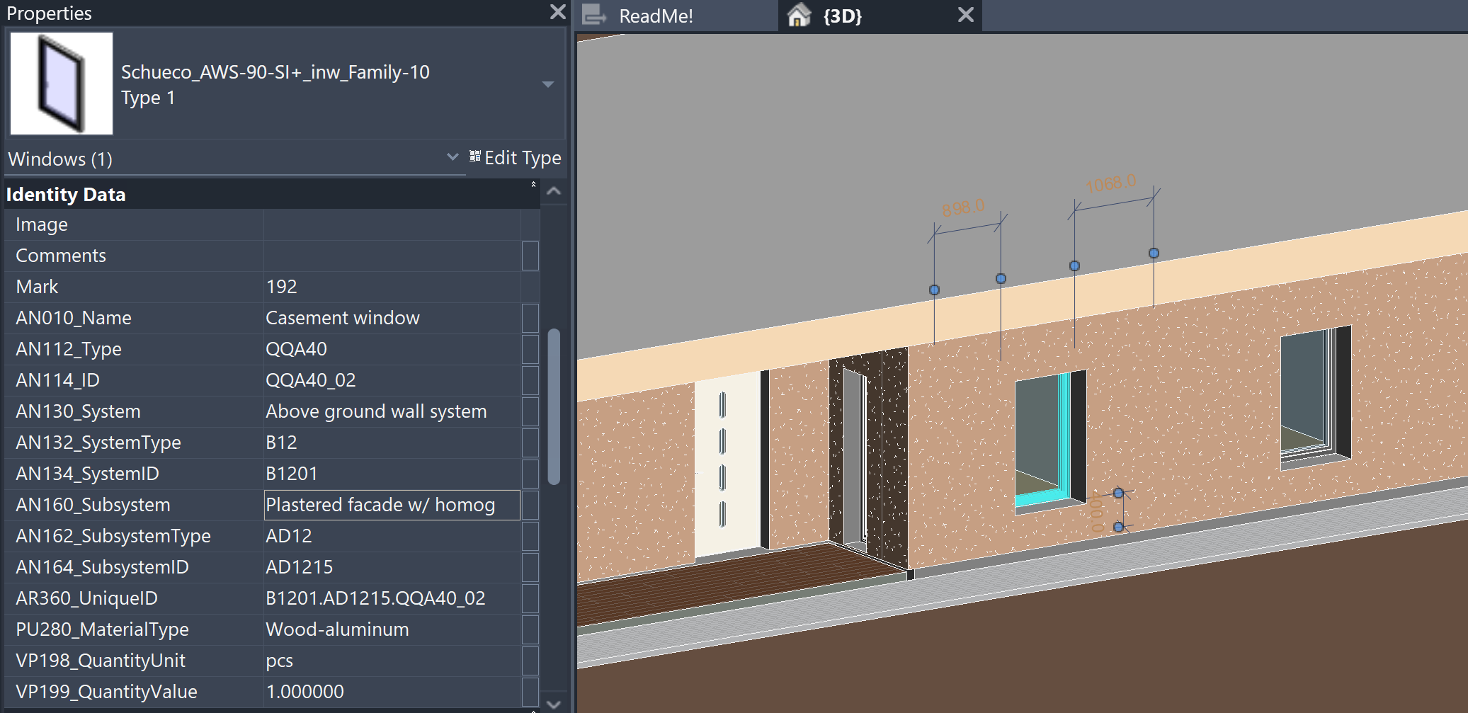
Using the example of a window as a component, we will therefore go through the attributes shown in the previous image, which also stipulates the rules for fulfilling these attributes.
- AN010_Name – window (type) name, which can be based on application tables (e.g. RDS/R). In this example: Casement window
- AN112_Type – type code corresponding to the window (type) name, which may be based on an existing application table (e.g. RDS/R). In this example: QQA40
- AN114_ID – a unique repetition of a specific window (of its type). Uniqueness can come both across the entire building, based on the type and its repetition, or also from the placement of a specific type of window in a system/subsystem. The final part (separated by an underscore) can also be expanded to three digits if necessary. In this example: QQA40_02
Essentially, this is all that is needed to classify a specific window. This is followed by the window’s relationship to the system and/or subsystem (belonging). The relationship/belonging allows components to be filtered by system. The system presents a broader view, so to speak (more general, e.g. horizontal-vertical arrangement), while the subsystem presents a narrower view (generally descriptive through a technical solution). Let’s see an example of a system first.
- AN130_System – human-readable name of the system (type), which can be based on application tables (e.g. RDS/R) or also on the client’s asset lists, in here as: Above ground wall system
- AN132_SystemType – machine-readable code of a system (type) that corresponds to a human-readable name and is based on the same source as the name itself. In this example, as: B12
- AN134_SystemID – a unique ID for a specific system type, allowing for the distinction between equivalent system types (across the building), in this example a two-digit number is used, which is written together with the system code. In this example as: B1201
Subsystems are “located” within systems, and their implementation follows similar principles to those of a system. The main difference is that the ID part now distinguishes unique subsystems within a particular system. So if the system changes, the subsystem can start again from the so-called “01” value. That is why components are classified into subsystems, and subsystems in turn into systems.
- AN160_Subsystem – human-readable name of the subsystem (type), which can be based on application tables (e.g. RDS/R) or also on the client’s asset lists, in here as: Plastered facade w/ homogeneous core
- AN162_SubsystemType – machine-readable code of a subsystem (type) that corresponds to a human-readable name and is based on the same source as the name itself. In this example, as: AD12
- AN164_SubsystemID – a unique ID for a specific subsystem type, allowing for the distinction between equivalent subsystem types (across a certain system), in this example a two-digit number is used, which is written together with the subsystem code. In this example as: AD1215
Once the component and its membership are defined, a unique ID value for a specific element can be created based on the individual values, which is based on RDS logic.
- AR360_UniqueID – this field contains individual ID values, which according to RDS logic are separated from each other by a period. In the given example as: B1201.AD1215.QQA40_01
Note. If necessary, the principles for creating a unique ID value can be changed, but this must be specified in the information requirements. For example, use an underscore for all ID values: B12_01.AD12_15.QQA40_01
Note. The unique ID value can also be supplemented with location-based or layout-related information. For example, with a window, we generally talk about the layout context (using the + sign). While a component in a room can be referenced as a location context (in this case, “++” or a double plus sign is used). Multiple reference groups can also be added to one property, but in this case they should be separated by the “/” sign: -B1201.AD1215.QQA40_01/+<CS>BAA1001
Note. See also the previous chapter. <CS> is a negotiable value. It can be replaced, for example, by the characters described by ISO 81346-12, but with certain differences/dimensions, and the choice of one or the other scheme must be clearly defined in the exchange information requirements.
In addition to the RDS/CCI classification attribute, some additional properties are included, with which we define, for example, the material category, the unit of base quantity calculation, and the quantity value (as a number, including the desired number of decimal places).
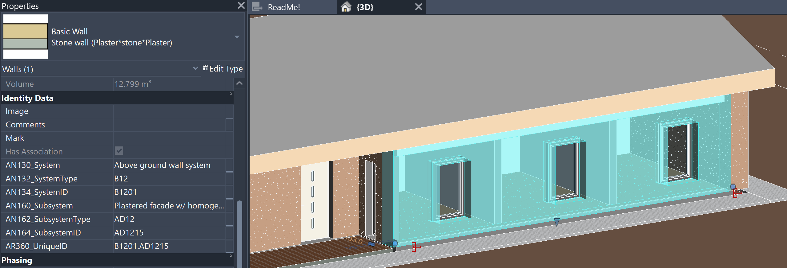
Building: Classification of a system (wall as an example of subsystem)
Below we have selected a wall in where we have previously classified the window. Essentially, the values presented here must correspond to those in the previous image, so they will not be repeated. However, note that if the wall changes, the values will also change. If the wall (subsystem) belongs to the same system, the system properties will remain the same. If the wall (subsystem) belongs to another system, the system properties will also change. Subsystems are generally modeled, while the system part is more general and is used as a grouping of subsystems, which is why we generally do not have such a component where we only fill in the part describing the system alone!
Building: Classification of a construction space
Below we have selected a room in a building that we have classified according to the RDS/CCI scheme.
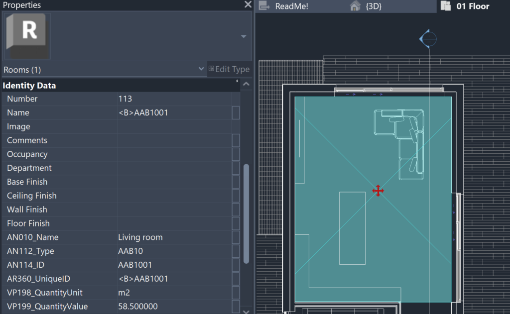
Let’s review which attributes must be filled in for a room as a built space (at a minimum). Since a room is an Instance type element in Autodesk Revit, there can be no double filling here (type vs single instance).
- AN010_Name – the name of the type of room built, based on the application table (RDS/R) or the client-based list/register. In this example as: Living room
- AN112_Type – the code for the type of built space that corresponds to the name and is based on the same source as the name itself. In this example as: AAB10
- AN114_ID – ID related to the type of built space, in which the so-called repetition of a space representing the same type is added with an additional two-digit number, here indicated as: AAB1001
- AR360_UniqueID – ID of the built space, to which a table code is additionally added, which allows them to be distinguished, for example, from other elements that represent 3 letters + 4 numbers, in order to include it in the creation of a specifying ID code (see window example)
In relation to the room, the unit-related property is also filled in, while the volumetric property is only filled in when exporting to IFC, and in the original model this value can be found in the default property. There is also a default property “Number” in use, which indicates the room number (additional requirement). In certain cases (e.g. public buildings), the AN114_ID property may be filled in in relation to the room number, in which the client/building specifics are used.
With this, we have provided an example of classification logic based on Autodesk Revit. The components are different and thus the previously discussed principles must also be used in the classification of other objects. The software specifics and template structure are described in a later section.
Bridge example
Below, we will carry out a basic classification exercise on the example of a bridge, where we will select one component. However, you can find a more complete picture in the downloadable Autodesk Revit file, where all similar components are classified, additional tables, etc. are included. The sample Revit file as well as the Shared Parameters file can be used to reuse attributes. In addition, the RDS/R (types table) is in use, which lists the types/subtypes used in the classification.
Note. The types/subtypes of the RDS/R table must be based on a uniform set of rules, e.g. a distinct function that the element performs or some other distinct aspect. Types/subtypes can always be specified with product-specific attributes (additional attributes), so RDS/R table types/subtypes must not be viewed in the context of product/manufacturer or overly specific attributes. However, in some cases, the distinguishing type/subtype can be the context of the material if such a distinction is very fundamental (e.g. environmental aspect). The RDS/R types table presented here is client-wide (possible to use across various clients), i.e. if you look at the type tables on the example of one specific client, it is obvious that they do not need to expand all RDS/CCI core classifiers into types/subtypes, but to limit themselves only to the parts that are important to them.
Bridge: Classification of a construction component (beam)
After RDS/CCI classification-related attributes are included in active project, those are displayed in the Properties > Identity Data section. Autodesk Revit is limited in that we can use built-in sections like Identity Data, IFC Parameters, Data etc. The display of attributes can be set based on the category of the object.
In the given examples, it is assumed that the required list of attributes is specified in the exchange information requirements. Some attributes are filled in individually, but with reference designation(s) or with unique ID, different values are combined into a single value (this can be automated, which will be discussed in further examples).
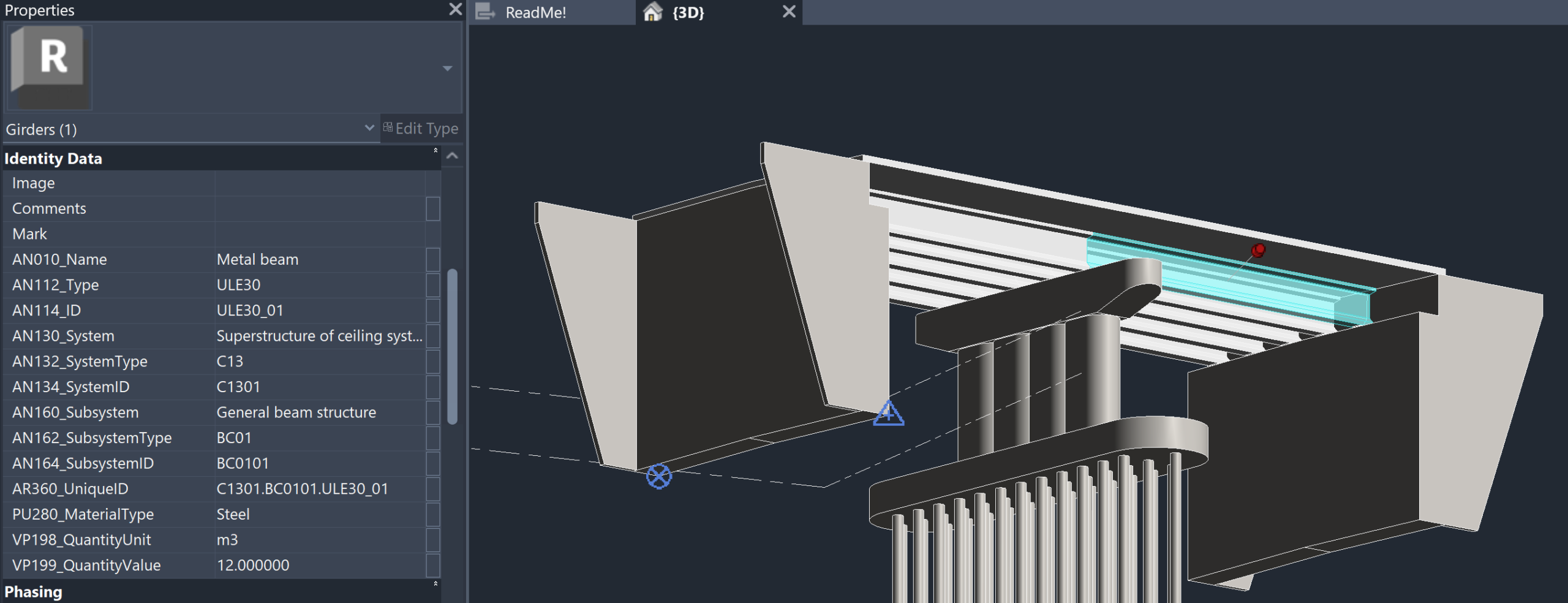
Using the example of a beam as a component, we will therefore go through the attributes shown in the previous image, which also stipulates the rules for fulfilling these attributes.
- AN010_Name – beam (type) name, which can be based on application tables (e.g. RDS/R). In this example: Metal beam
- AN112_Type – type code corresponding to the beam (type) name, which may be based on an existing application table (e.g. RDS/R). In this example: ULE30
- AN114_ID – a unique repetition of a specific beam (of its type). Uniqueness can come both across the entire construction entity, based on the type and its repetition, or also from the placement of a specific type of beam in a system/subsystem. The final part (separated by an underscore) can also be expanded to three digits if necessary. In this example: ULE30_01
Essentially, this is all that is needed to classify a specific beam. This is followed by the beam’s relationship to the system and/or subsystem (belonging). The relationship/belonging allows components to be filtered by system. The system presents a broader view, so to speak (more general, e.g. horizontal-vertical arrangement), while the subsystem presents a narrower view (generally descriptive through a technical solution). Let’s see an example of a system first.
- AN130_System – human-readable name of the system (type), which can be based on application tables (e.g. RDS/R) or also on the client’s asset lists, in here as: Superstructure of ceiling system
- AN132_SystemType – machine-readable code of a system (type) that corresponds to a human-readable name and is based on the same source as the name itself. In this example, as: C13
- AN134_SystemID – a unique ID for a specific system type, allowing for the distinction between equivalent system types (across the construction entity), in this example a two-digit number is used, which is written together with the system code. In this example as: C1301
Subsystems are “located” within systems, and their implementation follows similar principles to those of a system. The main difference is that the ID part now distinguishes unique subsystems within a particular system. So if the system changes, the subsystem can start again from the so-called “01” value. That is why components are classified into subsystems, and subsystems in turn into systems.
- AN160_Subsystem – human-readable name of the subsystem (type), which can be based on application tables (e.g. RDS/R) or also on the client’s asset lists, in here as: General beam structure
- AN162_SubsystemType – machine-readable code of a subsystem (type) that corresponds to a human-readable name and is based on the same source as the name itself. In this example, as: BC01
- AN164_SubsystemID – a unique ID for a specific subsystem type, allowing for the distinction between equivalent subsystem types (across a certain system), in this example a two-digit number is used, which is written together with the subsystem code. In this example as: BC0101
Once the component and its membership are defined, a unique ID value for a specific element can be created based on the individual values, which is based on RDS logic.
- AR360_UniqueID – this field contains individual ID values, which according to RDS logic are separated from each other by a period. In the given example as: C1301.BC0101.ULE30_01
Note. If necessary, the principles for creating a unique ID value can be changed, but this must be specified in the information requirements. For example, use an underscore for all ID values: C13_01.BC01_01.ULE30_01
Note. The unique ID value can also be supplemented with location-based or layout-related information.
In addition to the RDS/CCI classification attribute, some additional properties are included, with which we define, for example, the material category, the unit of base quantity calculation, and the quantity value (as a number, including the desired number of decimal places).
With this, we have presented an example of the classification logic of a bridge based on Autodesk Revit. The components are different and therefore the principles discussed previously must be used when classifying other objects as well. The software specifics and the structure of the templates are described in a later section.